zombiess said:
I did some testing of the current my gate driver can deliver. Setup is as follows.
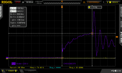
I setup a 104mOhm shunt (10x 1.0 ohm resistors) in parallel with the gate drive output hooked up to a 1.0uF snubber cap. The boost stage has 2 10uF caps in parallel feeding it. The 1.0uF cap was used because it was handy and low enough ESR to get a high peak current. I need to parallel several small caps to see how quickly the current can rise. With a 0.1 Ohm gate resistor I managed 14.4A out in 570nS and 13.6A drained from the gate in 960nS which doesn't seem too bad for a giant capacitive load. Now I have some idea about the current rise rate (still needs more testing for rise time). It's no IXYS IXD-614 for speed, but it has some kick ass safety features integrated vs just being a bare gate driver.
On (purple trace is current and is channel B which is my math function.
View attachment 1
I had a look over the circuits and have some questions / thoughts.
Why did you put the DC/DC on a seperate sheet?
Where you thinking of making a DC/DC?
Why have the Gplane connector?
If its for support .. just leave it nc.
REduce chance off current loops.
No cap on Vref pin?
Digital On input from brain could have 100ohm terminator to 0V before the 330R and small cap.
To stop opto false triggering.... but there is filtering on the isolated side and in the TD350.
Parts could be there just nor fitted.
Fault signal protection of opto output?
Why are the td350 NC 4,6 pins conneceted to common?
Why did you choose boosy with emitters linked?
Will Ron/off (R22) get much hotter than Roff r26 and Diode d14??
Clamp circuit has a very long path. Do you see pulses on the Gate signal?
Gate damping cap .. will see lots of pulse currents ... is the type for this.
But it is so far from gate and via 0R5 res's that it wont see the Ccg currents from dV/dt
causing Vcg effects that the clamp is to protect for.
The Zetex Clamp transistor looks very fast on the spec.
Would be interesting to see its Vce signal.
C102 on one phase is linked for mid layer ... but not fitted??
Was mid layer needed ... was it thinner copper??
Why did you link like you did??
It doesn't make sense as a laminated return path.
Too many 90deg corners for me on power flow tracks. chamfers and fillets.
Would yuo be tempted to try to fit a 24 fet into the hammond case.
Your phase boards could fit 4 parallel.
Did you see much overshoot on the FET's
What did the Gate signal look like.
How much delay was there from say the haz side of the opto to turn on/off?
What voltage HV power Caps did you fit?
How did you wire the HASS 600A Current sensors?
Did you get to study the Phase voltage and current on the scope?
These are just some thoughts no need to measure anything.
Just consider them for you next design.
Nice design work Zombiess.
Are you getting good use out of the bike setup?
7C


