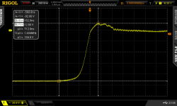
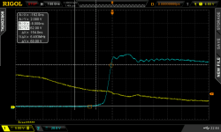
I think I've figured out why adding a gate-source cap works to reduce turn off overshoot. I'm couldn't find any good explanations of what causes turn off ringing so I took a stab at figuring it out myself. I hope I got this correct.
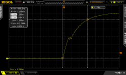
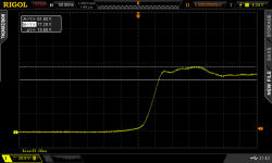
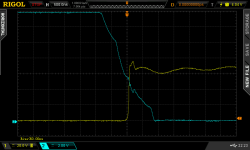
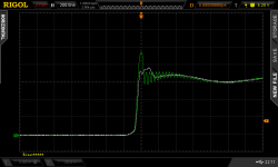
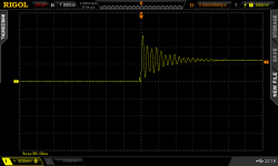
This is a picture of the problem. Notice the big 33V overshoot at turn off on the drain to source scope shot. Also not the dip on the gate to source connection. This was done with no gate to source capacitor installed. I saw this same type of dip on the gate source trace of my previous controller build.
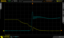
This is what I believe is happening in the above screen shot.
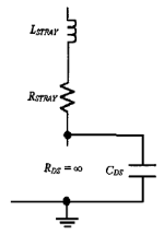
As the MOSFET turns off, the current it was conducting has no where to go, so the voltage shoots up from this high current reacting with the parasitic inductance in the circuit. Since the current was stopped, the magnetic field starts to collapse. A collapsing magnetic field switches to the opposite polarity of what charged it. The D-S connection now has it's parasitic D-S capacitor (Cgd) pulled negative very quickly which causes the G-S (Cgs) parasitic capacitor to discharge and revesre. The G-S becomes fully discharged which shuts off the current flow D-S. The gate to source was already transitioning through the trans conductance region and RDSon is quickly headed towards becoming very high impedance which causes the D-S spike to reverse direction and head back towards the bus voltage. The parasitic Cds and respective Cgs and Cgd capacitance's start to reverse their polarity back to the state they were originally in and charge up again (from being negative), the Cds capacitor rises as it get pulled back to bus voltage. The parasitic inductance in the leads and components add to this as it's field collapses as it switches back polarity as well. Since the MOSFET is now high impedance, the magnetic field has no where to go so the process repeats, but at a lower magnitude. This is seen as ringing after the initial spike. The turn off spike can only last from the time Vds crosses Vbus to the time Vgs reaches the Vgsth threshold which I have previously measured at around 3.4v. This is within the spec sheet value of 3-5V for Vgsth. The reason it can only go back to Vgsth is the circuit has now been shut off and no more energy can enter, only the residual energy within the parasitics are left and they dissipate over the next few micro seconds as ringing dampened only by the parasitic resistance.
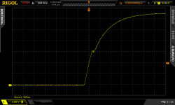
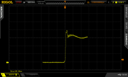
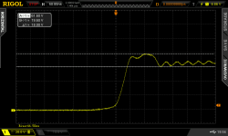
Now enter external the gate to source capacitor. All the above still happens, but when Vgs tries to reverse, there is additional capacitance which has been added. This extra capacitance takes longer to discharge which helps prevent the spike because the gate voltage is kept up by the capacitor which resisting the polarity change that tries to happen as the magnetic field collapses and increases the Cgs discharge time. As can be seen in the below screen shot, a polarity change does happen driving Vgs lower for about 200ns, but it's much less than previously seen since it takes more time to discharge the additional capacitor. The previous 36v spike above Vbus is now limited to ~16 volts.
Turn off shot after a 280A on pulse, a single 68nF capacitor was added to a central connection point of the gate & source pins for all 3 MOSFETs.

Comparison of Vgs using a 68nF (purple trace) and 0nF (orange trace)
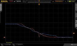
Comparison of Vds using 68nF (white trace) and 0nF (green trace)
Benefits
1. Reduces turn off overshoot allowing a higher maximum voltage rating due to the extra head room
2. Stretches and flattens out turn off overshoot which reduces RFI
3. Produces less ringing at turn on/off
4. Allows the switching speeds to be pushed faster while maintaining a clean waveform.
Negatives
1. It can require a more powerful gate driver to switch on effectively than would otherwise be required for the given gate charge.
2. If a Miller clamp is not used, this capacitor could be charged up over time by stray inductance leading to the MOSFET Vgsth being reached and turning on causing a shoot through event.
3. Has a small effect on the Miller charge causing longer switch times.
The common method to stop a drain to source turn off spike and subsequent ringing is to increase the gate resistor slowing down the turn off time. The sharp turn off spike also means more emitted RFI, lower maximum bus voltage with regard to part rating, higher switching losses and reduced operating power. Adding external gate to source capacitance appears to improve all of the these issues substantially.
Now on to the Miller clamp feature.
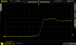
Scoped the opposite gate drive to the one I was firing. I first did it without any power so the Miller clamp was disabled. Discharging ~500A
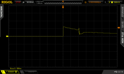
This is a zoomed in shot showing the wave form. Voltage creeps up to 0.6 volts when discharging ~500A
Gate driver powered, Miller clamp turned on, the voltage is significantly reduced when discharging ~500A
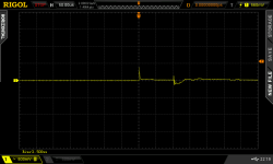
About half of the spike is probably CMRR as I did check it, but didn't get a scope shot. There was certainly some present, about 0.25V worth.


