• Hello ES! We could use some help to get us past the finish line on building the new knowledgebase for the forum.
    Can you donate? Please see our fundraising page. Thank you!

Luna M600 Ludicrous V2 reverse engineering and firmware making

For anyone reading this looking into the innotrace saga

By the grace of Benjamin Vedder, there is the open source firmware for the innotrace x1. Installing it won't be easy, you'll need to access the SWD and it might involve wiring and breaking seals and configuring with the included lisp script, with risk of bricking things, but it's there. I've tested it personally, it works with enough enthusiasm and effort.

Now...

Regarding this saga of "reverse engineering"... There is absolutely no way in hell anyone with the capability of the purported level of engineering is unable to get the firmware working. It's just inconceivable.

This leads to the logical conclusion, with the bizarre behaviour and mysterious firmware supply that the efforts are a ruse to dampen and delay anyone's frustration with being screwed out of a working bike.

This Luna reverse engineering appears to be nothing more than spite at a competitor... Luna have AFAIK honoured GPL requirements (hardware is not covered by GPL and the creator of the luna board is plenty capable of making his own VESC compatible design) and have their firmware pushed to the main VESC repo

So... If you're an unfortunate x1 customer with a bricked/locked out bike, your primary options seem to be significant personal effort and risk flashing open VESC firmware from the repo linked above or to persue legal action to get the situation sorted.
Can you please connect an St-Link to the Innotrace controller you were able to make works with the VESC firmware, connect it to St-Link utility and dump the STM32 memory image and post it here. That will help us to skip all those steps with VESC configurations and just clone your working controller.

You basically need to do what I did here

 
Last edited:
For anyone reading this looking into the innotrace saga

By the grace of Benjamin Vedder, there is the open source firmware for the innotrace x1. Installing it won't be easy, you'll need to access the SWD and it might involve wiring and breaking seals and configuring with the included lisp script, with risk of bricking things, but it's there. I've tested it personally, it works with enough enthusiasm and effort.

Now...

Regarding this saga of "reverse engineering"... There is absolutely no way in hell anyone with the capability of the purported level of engineering is unable to get the firmware working. It's just inconceivable.

This leads to the logical conclusion, with the bizarre behaviour and mysterious firmware supply that the efforts are a ruse to dampen and delay anyone's frustration with being screwed out of a working bike.

This Luna reverse engineering appears to be nothing more than spite at a competitor... Luna have AFAIK honoured GPL requirements (hardware is not covered by GPL and the creator of the luna board is plenty capable of making his own VESC compatible design) and have their firmware pushed to the main VESC repo

So... If you're an unfortunate x1 customer with a bricked/locked out bike, your primary options seem to be significant personal effort and risk flashing open VESC firmware from the repo linked above or to persue legal action to get the situation sorted.
Alright... so how does it ride?
 
Sounds good. I’ll take a closer look at it and maybe give it a try. Where can I find the Lisp script? At first glance, I didn’t even spot it.
Here are the bin files with Lisp code and motor configuration.


Please post the instructions and the STM32 memory image if you make it works. I was not able to make it works.
 
Last edited:
Thanks. Did you try it on the original X1 hardware or on your reengineered one?
I tried it on the reverse engineered (because of it is more convenient, I made CAN interface power supply for VESC Express, convenient connector for ST-Link and USB interface).
 
I tried it on the reverse engineered (because of it is more convenient, I made CAN interface power supply for VESC Express, convenient connector for ST-Link and USB interface).
Could it maybe be your hardware then? I’m guessing Mxlemmig used an original X1.
 
Could it maybe be your hardware then? I’m guessing Mxlemmig used an original X1.
If I will know how to install it I can tell for sure. But I do not know how to install it, they did not post instructions. There are no even clear instructions how to connect the VESC Express and I figured it out just accidentally (the way Benjamin Vedder shows it in his video and how it is shown in the VESC Express documentation simply does not work).
 
Last edited:
If I will know how to install it I can tell for sure. But I do not know how to install it, they did not post instructions. There are no even clear instructions how to connect the VESC Express and I figured it out just accidentally (the way Benjamin Vedder shows it in his video and how it is shown in the VESC Express documentation simply does not work).
Why do you think the community is putting so much pressure on you to release the extracted firmware? If the VESC firmware really works now, there’s no reason anymore, is there?
 
Why do you think the community is putting so much pressure on you to release the extracted firmware? If the VESC firmware really works now, there’s no reason anymore, is there?
I guess the VESC firmware is underdeveloped and it does not work quite well and they can not finish it to be as good as the Innotrace firmware. I also believe they are not motivated to finish the work even I offered to help them to test their VESC firmware and provided the information about the purpose of each circuit of the Innotrace controller. Instead of finishing the open source VESC firmware they just want to go the simple way. So they want just to obtain the Innotrace firmware and call it the day.
 
Last edited:
I guess the VESC firmware is underdeveloped and it does not work quite well and they can not finish it to be as good as the Innotrace firmware. I also believe they are not motivated to finish the work even I offered to help them to test their VESC firmware. Instead of finishing the open source VESC firmware they just want to go the simple way. So they want just obtain the Innotrace firmware and call it the day.
I see. I'm not sure there isn't more going on behind the scenes. I got kicked out of the Discord chat after just one post. Seems like some people there just can’t handle the truth. But oh well...
 
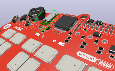
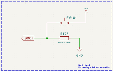
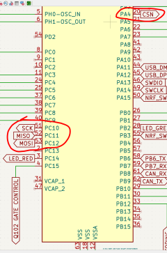
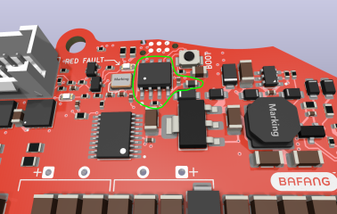
The controller recovery circuit has been reverse engineered.

Luna deleted this switch on the latest revisions because of that switch can be accidentally pressed by wires during installation the controller into the M600 case. But we can keep it for convenience and just simply cover it by a 3D printed cap or something to protect if from accidental actuation.

1752677001540.png

1752677125460.png

1752677174907.png

1752677283666.png
 
marcos from luna
Hey, mxlemming, can you please contact marcos and ask him about the differences between the Luna Rev7 and Rev6. I just realized the latest revision is actually Rev7 (according to the Luna 2025 manual) and the controller I got is Rev6.

Ideally you need to ask him to provide you with the schematics. I asked marcos for schematics but had no luck, but he might share them with you because of he probably trusts you. You can share the schematics privately with me and we can use them to match the latest Luna improvements. I can make it looks like I figured out those improvements on myself if you think sharing the original schematics openly will harm your relations with marcos.

1752678910654.png
 
Last edited:
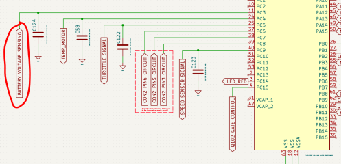
Hmm thats strange, why they played with temp sensor connector and using unused pins. Could be also prepared for normal 3 stator halls as it goes to STM. If this is the case and was prepared for 3x halls then more just like pull up resistor than voltage divider. Just 10k resistors to STM pins 3,5,6 I find quit high. Lets see if rotary magnet sensor U104 is working.
The rotary magnet sensor circuits have been reverse engineered!

1752717698656.png

1752717777023.png

1752717896422.png
 
Last edited:
Almighty guys, we are getting dangerously close to finishing the schematics. Now it is time to complete the reverse engineering of the the power stage. If somebody knows a neat trick figuring out the Kelvin Connections without using soldering iron please let me know.

What is the chance these two vias are Kelvin Connectors? There is the same pattern on all three phases. Any VESC experts here? It is not quite correct way to place the Kelvin Connectors but do you think it will affect the work of the controller if I will place the connectors the right way while the Luna firmware might be tuned for the wrong way?

1752722922549.png

Looking on top and bottom footprints combined I would say the chance Luna did the Kelvin connectors the wrong way is quite high. But as long as it works who cares, right?

1752723971086.png

On the older Luna revisions they did the Kelvin connectors a bit more appropriately, but still not quite right

1752724865390.png
 
Last edited:
There is weird thing going on with the current amplifier on the controller. It looks like I figured out the pattern for the shunts Kelvin connections but the most logical way it would be connected would caused the High site of the shunts will be connected to "IN-" pins of the amplifier and the Low side of the shunts will be connected to "IN+" pins of the current amplifier which is opposite to how it supposed to be. If connect it the correct way then the tracks will cross each other or will require twist to be connected properly for all three phases while it could be avoided simply by swapping the Kelvin connectors positions.

Do you think Lina connected the Kelvin connectors on the shunts opposite way? Does it affect anything? Can it be fixed in the firmware?


1752734672980.png

1752734615316.png
 
Or maybe Luna placed the current sensing tracks on different layers of the PCB crossing them to solve the PCB parasitic issues?

1752764554979.png
 
The VESC is capable of regenerative braking, in which case the shunt is used to measure current and the direction of flow. If you swap the connections so they don’t cross, the shunt reading needs to be interpreted accordingly in the software. That’s how it should work, based on my intuition.
 
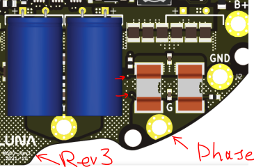
Please also note the shunts on the Ref6 of the Luna controller are placed on the low side while the earlier versions of the Luna controller (Rev3 for instance) have shunts places on the phases wires

1752784705635.png

1752784615077.png
 
OK guys, for the sake of the truth I lifted the shunts on the phase C circuit and yup, those two vias are Kelvin connections and yup, they just followed the straight most logical pattern and connected the current-sense amplifier straight and with wrong polarity (connected the low side to "IN+" and the high side to "IN-". Things about this controller are getting weirder.

So what do you think guys, does this controller work at all (I did not test it before cracking it open)?

1752813811336.png

1752813871137.png

1752814448320.png

1752814609007.png

1752814679498.png

1752814834072.png
 
I checked and my flipsky mini also has a shunt on the low side it is compatible with Vesc 6.6
 

Attachments

  • FLIPSKY Mini FSESC6.7 PRO 70A podstawa na VESC®6.6.jpg
    FLIPSKY Mini FSESC6.7 PRO 70A podstawa na VESC®6.6.jpg
    45.6 KB · Views: 9
Back
Top