• Hello ES! We could use some help to get us past the finish line on building the new knowledgebase for the forum.
    Can you donate? Please see our fundraising page. Thank you!

Luna M600 Ludicrous V2 reverse engineering and firmware making

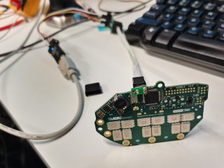
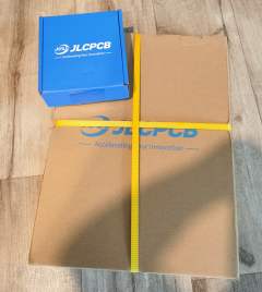
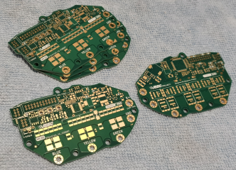
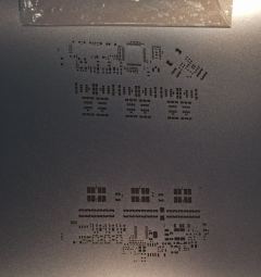
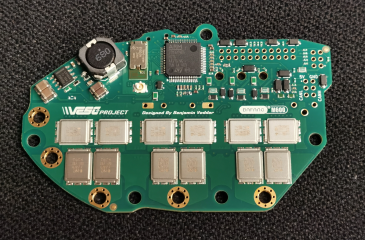
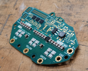
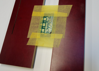
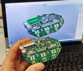
Alright, the PCBs, stencils and the CNC machined cover have been ordered. It is the time to get excited, fingers crossed!

I also updated the KiCAD files (included the heat pad CAD model, fixed some mistakes and did some other adjustments).


If you want to order the PCB you can use the Gerber files I generated. The zip file with the Gerber files are in the archive (there is no guarantee it will work though, we need to test it).

1754537804198.png


1754535635465.png

1754535742607.png

1754535835624.png

1754536661144.png
 
How much are components in total? Would be possible to make it also 4 layers, no?

Why not to let them place components. Still wondering why people are doing it by hand. Must be a pain with small SMD components.
 
5 PCBs and stensils are about $40 without shipping, the cover is about $40 without shipping. I did not order other components yet but those are probably around $70-100.

Without changing external layers I do not see how it is possible to make it 4 layers. With changing the external layers and a lot of elbow grease it might be possible.

Letting them to solder components is quite expensive and waistful if you need just one board (you will pay extra for the waist pick and place machine requires). It also will take extra time for them to order and assemble the components. They also will likely struggle finding some components and you have to spent time communicating with them figuring out the assembly issues. You might need also to send them the components they were not able to find which is again extra time and hassle and room for mistakes. It is quite a process. Soldering manually allows you not only save a lot of money and time if you need just one board but also inspect the board and find mistakes you missed during reverse engineering.
 
Last edited:
100USD is not bad, looking forward. I have noticed jlc is slowly raising shipping.
 
Is anybody actually running vesc firmware on their X1? Flashing via vesc express seems simple enough. I am tempted to try it, but I don't want to lose functionality. Has anybody tweaked the Lisp script or is it in the same state as before?
 
Is anybody actually running vesc firmware on their X1? Flashing via vesc express seems simple enough. I am tempted to try it, but I don't want to lose functionality. Has anybody tweaked the Lisp script or is it in the same state as before?
Yes, the VESC team guys use the VESC firmware with Innotrace controller according to their claim. They do not share the instructions how to use it though, at least with me. You can try to ask them on the VESC Discord server.

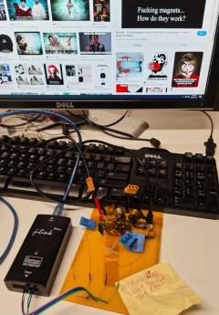
VESC Express dongle is not for flashing, it is for further setup after flashing. You need to open the motor and flash the controller with ST-Link V2 dongle and Tag Connect cable first. Once the controller is flashed you need to figure out how to power the VESC Express with 5V (it requires 5V and it looks like it does not take it from USB cable, at least I was not able to make it works with USB cable alone. I ended up trying to use VESC Express on the reverse engineered Innotrace controller where I modified the CAN interface connector circuit and added 5V power source to it).
 
Last edited:
Yes, the VESC team guys use the VESC firmware with Innotrace controller according to their claim. They do not share the instructions how to use it though, at least with me. You can try to ask them on the VESC Discord server.

VESC Express dongle is not for flashing, it is for further setup after flashing. You need to open the motor and flash the controller with ST-Link V2 dongle and Tag Connect cable first. Once the controller is flashed you need to figure out how to power the VESC Express with 5V (it requires 5V and it looks like it does not take it from USB cable, at least I was not able to make it works with USB cable alone. I ended up trying to use VESC Express on the reverse engineered Innotrace controller where I modified the CAN interface connector circuit and added 5V power source to it).
Thanks, then I will wait for until I have to do maintenance on the motor
 
Still waiting for other components before we can start soldering the controller
What is the plan once you solder everything up? You'll flash the exact same image to it and check if it works the same as the original controller?
 
What is the plan once you solder everything up? You'll flash the exact same image to it and check if it works the same as the original controller?
Yes, the plan is to flash the same image on the STM32 chip on the new controller. Then we need to figure out how to flash the Bluetooth module (it looks like the controller can be connected to VESC Tool with USB cable and the VESC Tool detects the Bluetooth module and offers different firmwares for flashing it from The VESC Tool interface). I guess the Luna controller uses the standard code from VESC for Bluetooth. If not, then we need to unsolder the Bluetooth module from the original Luna controller and dump the firmware from the NRF51822 chip and use it to flash the Bluetooth module on the new controller.

Then we need to install the new controller into the motor and connect it to the battery and see if it spins like the original one. Then we need to install everything in the bicycle frame and see if it works properly. I ordered a Markhor Kunlun frame to test it. We might need to assemble a custom battery for it because of the original Kulnul Bafang battery is only 48V 25A which is quite low power.
 
Last edited:
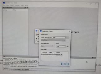
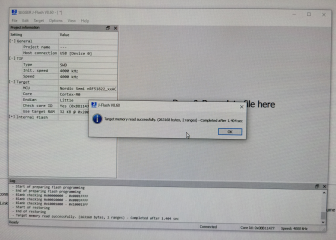
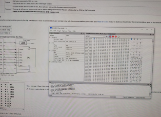
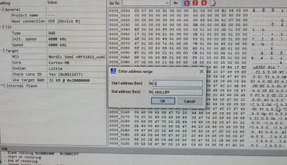
Alrighty guys. Since waiting those last bits from China takes forever I decided to extract the firmware from the Luna Bluetooth module in the meantime. Here are the images in *.bin , *.hex and *.jflash formats. We need to save these files because of it is our base point the gold standard. If you want to flash the Bluetooth with USB cable and VESC Tool you probably need to use the file "Bluetooth Firmware from Ludicrous v2 m600 2022 Rev5 dumped from nRF51822_xxAC_256kB Flash_32kB RAM_Trimmed_2025-08-18.bin" from the archive


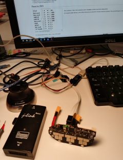
The extraction was executed with J-Link programmer and J-Flash program. So if Luna uses a special Bluetooth firmware or flashing the Bluetooth with VESC will not work at least we have an opportunity to clone it the hardcore way.

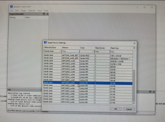
It looks like the chip in the Bluetooth module is nRF51822_xxAC with 256kB Flash and 32kB RAM.

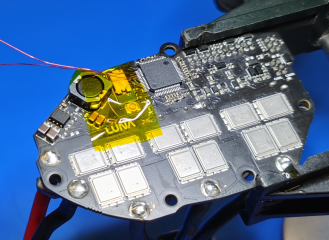
I decided not to unsolder the Bluetooth module and just erased the STM32 chip with ST-Link V2 to avoid interference and extracted the firmware with J-Link soldering the wires to the exposed traces from the Bluetooth module pins and powering the board (and the Bluetooth module) with USB cable.

1755327746719.png

1755327852869.png

1755331926719.png


1755328014666.png


1755328050961.png

1755328125239.png

1755328162648.png

1755328189523.png

1755330299148.png
 
Last edited:
Finally the last bits for the PCB are here so we can start soldering the board. The Bluetooth and the rotary encoder can be purchased only in China

1755561913858.png
 
Last edited:
We are getting closer guys! The progress on the top face for today

1755758810878.png

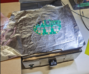
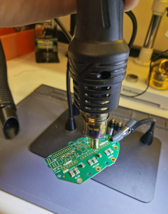
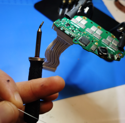
I applied the soldering paste only on the top face of the power stage and soldered it with the hot air. The rest is soldered manually mostly with soldering irons.

For soldering the top face I used a 3D printed jig. I will put the jig CAD model in the archive with the files with next update if everything will work good and won't require modifications so you can use it for convenience if you want to

1755758954600.png

1755758979609.png

1755759056634.png

Applied the soldering paste only on the power stage and soldered it with hot air applying the heat only locally

1755759125739.png

1755759186838.png

1755759215711.png

The MOSFET drivers should be soldered specific way. First you solder the pins so it holds the chip in place.

1755759327793.png

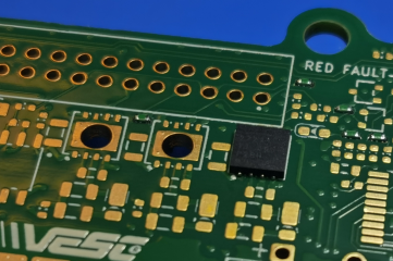
Then you flip the board and solder the bottom pad through the hole. You have to make sure you wet the bottom pad of the chip with solder and there is solder joint between the hole walls and the bottom pad of the chip. Once you wet both surfaces you have to stop applying any pressure on the bottom pad of the chip with the soldering iron tip to avoid dislodging the chip (the soldering joints on the chip pins can be melted because of the chip is small and you do not want to move the chip). Then you fill the hole with solder.

1755759913241.png

1755759952261.png

1755760007148.png

1755760032066.png
 
Woohoo! All SMD components have been soldered and Bluetooth with VESC Tool communications work!

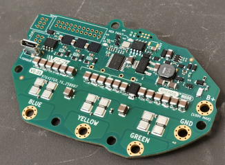
1755851973696.png

1755852134184.png

Unfortunately I was not able to make the Bluetooth works using the VESC Tool (using the "SWD Programmer" menu in the VESC Tool and "Connect Internal" to connect the Bluetooth chip). I tried all the firmware files the VESC Tool offered (4 different options) and none of them made it works. I also tried to flash the Bluetooth module with VESC Tool using the *.hex file and the trimmed *.bin file I extracted from the original Luna Bluetooth module and it did not work either. I do not know what the problem is, maybe VESC tool is just not capable to do this operation properly, or maybe Luna uses proprietary firmware VESC tool does not offer.

I also do not see the Luna Bluetooth module firmware here


So currently the only way to make the Bluetooth works is to use brute force. But no worries, I will explain you how to do this.

Here is the process:

1) Once you soldered the controller do not flash the firmware on the STM32. If you flashed it already then erase it.

2) Solder 4 tiny wires to Ground, 3.3V, Bluetooth module SWCLK pin (Pin #50 on STM32 is connected to it and can be used for soldering the wire), Bluetooth module SWDIO pin (Pin #55 on STM32 is connected to it and can be used for soldering the wire)
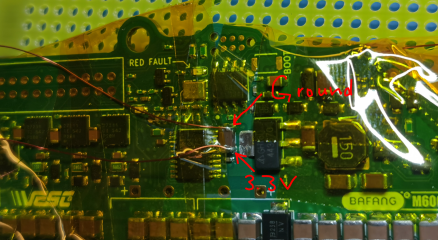
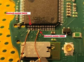
1755853212315.png

1755853342679.png


3) Connect those 4 wires to J-Link Ultra+ programmer

1755853592209.png

1755853871478.png

4) Connect USB cable to the USB receptacle on the controller and connect other end of the USB cable to USB port in powered PC (this is for powering the Bluetooth module)
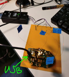
1755853714797.png

5) Connect J-Link Ultra+ to PC with USB cable.

6) Download and install J-Link Software and Documentation pack for your system


7) After installation open J-Flash program (installed with the J-Link Software and Documentation pack) and select "Create new project ---> Start J-Flash", then select "Target Device" as nRF51822_xxAC, the rest of the options keep as is.

Or you can just open the project file "Bluetooth Firmware from Ludicrous v2 m600 2022 Rev5 dumped from nRF51822_xxAC_256kB Flash_32kB RAM_2025-08-18.jflash" on the J-Flash program start from the Bluetooth firmware archive I shared earlier.


8) In the J-Flash program select "Target ---> Connect"

9) Then select "Target ---> Manual Programming ---> Erase Chip"

10) Then select "File --> Open data File" and select the "Bluetooth Firmware from Ludicrous v2 m600 2022 Rev5 dumped from nRF51822_xxAC_256kB Flash_32kB RAM_2025-08-15.hex" file from the Bluetooth firmware archive I shared earlier.
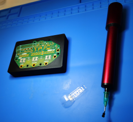

11) Then select "Target ---> Manual Programming ---> Program & Verify"

12) After finishing the process select "Target ---> Disconnect"

13) Disconnect the controller from the cables and unsolder the 4 wires from the controller you soldered for this process before

14) Now you can flash the STM32 with the controller VESC firmware image I shared with ST-Link V2 dongle and Tag Connect cable usual way connecting the ST-Link V2 dongle following the pin-out of the Tag Connect pads from the controller Ki-CAD files


1755854672836.png
 
Last edited:
The connectors are on the PCB!

1755986974054.png

1755987005120.png

I recommend to crimp a plug and stick it in the connectors during soldering to avoid shifting the pins due to softened plastic of the connectors housings at high temperature

1755986937111.png

1755987050003.png

1755987074240.png

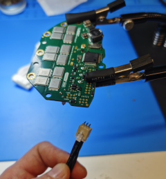
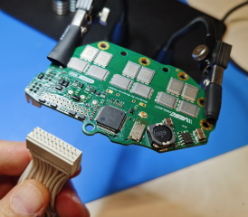
For the 22 pins connector you can use the harness from the Bafang motor

1755987105244.png


1755987150874.png
 
Last edited:
The leads have been soldered!

1755992748309.png

1755992814729.png

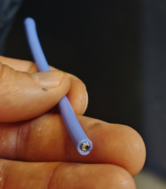
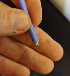
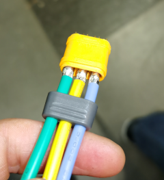
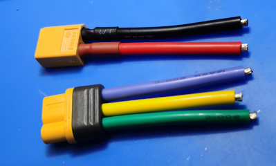
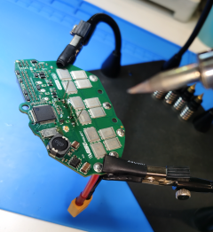
Here is the process. You chop 12AWG silicone wires with extra length. Put a little tin on one end of the wire before stripping the insulation

1755992949768.png

1755992964061.png

Strip the insulation

1755992983197.png

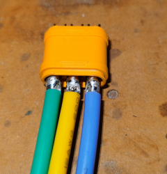
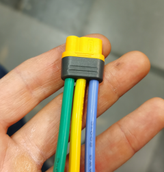
Solder the wires to the plugs

1755993026197.png

Assemble the plug

1755993048300.png

1755993062244.png

Trim the wires to necessary length

1755993295339.png

Tin and strip the wires ends

1755993800884.png

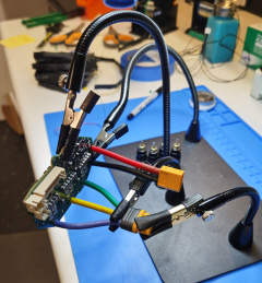
Solder the wires to the PCB. I also recommend to tin the soldering pads before soldering the wires to it.

1755993347348.png
 
Last edited:
The bulk capacitors have been soldered! and the PCB is complete!

1755996235695.png

1755996265984.png

Here is the process.

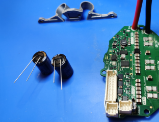
3D print the capacitors clip out of ABS plastic

1755996348139.png

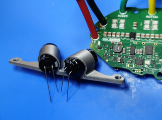
Bend the capacitors legs making sure the proper polarity when you install them.

1755996437847.png

Attach the capacitors to the clip and attach it to the PCB

1755996495537.png

1755996517136.png

Solder the capacitors

1755996552344.png

Trim the legs and clean the board in alcohol real good

1755996587086.png
 
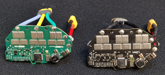
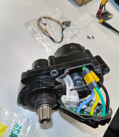
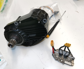
I think it is a good idea to take some images before I burned this thing to the ground. If something will happen after plugging it to the power at least we will have some happy memory pictures.

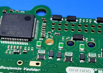
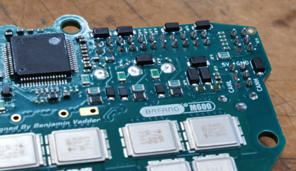
There you have it guys, the original vs the counterfeit. Which one do you prefer?

1755998351689.png

1755998392876.png

1755998465424.png
 
Installing the controller. We better be prepared guys!

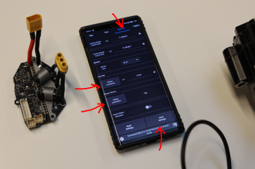
Just to be safe connected the controller to PC with USB cable once again and changed the settings of the battery to 14S (the one I am going to use for test)

1756002146148.png

1756002190250.png

I am still waiting the CNC machined cover from China so I decided to assemble it with the original Luna cover.

1756002217178.png

Everything fits like a glove as expected!


1756002279765.png

1756002327723.png

1756002351169.png


Wish me luck guys!

1756002392429.png
 
Holy cow, it works! We did it guys! Unbelievable!

1756003972817.png

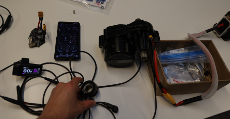
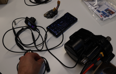
Just connected the battery, turned the display ON, connected the phone with Bluetooth through the VESC Tool application, calibrated the rotary encoder, calibrated the torque sensor, wrote the settings and it spins just like the original one!

1756004255581.png

The speed sensor works also!

1756004324085.png

Thanks to everyone who participated in this epic effort! I think we deserve to go an celebrate this milestone! The next step is the most fun part, building the bike and testing it in the wild!
 
Holy cow, it works! We did it guys! Unbelievable!

View attachment 376105

Just connected the battery, turned the display ON, connected the phone with Bluetooth through the VESC Tool application, calibrated the rotary encoder, calibrated the torque sensor, wrote the settings and it spins just like the original one!

View attachment 376106

The speed sensor works also!

View attachment 376107

Thanks to everyone who participated in this epic effort! I think we deserve to go an celebrate this milestone! The next step is the most fun part, building the bike and testing it in the wild!
Great job, I really appreciate how much time and energy you put into this project. This is rocket science already – and you nailed it! 😄
 
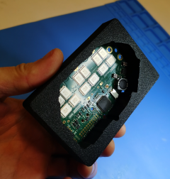
The CNC machined aluminum cover from JLCCNC has finally arrived and looks pristine with nice matte black anodized finish! No tooling marks, no nothing, just perfect! Will see how it fits.

1756081319703.png

1756081380091.png
 
Last edited:
Your work is art.

 
Last edited:
Back
Top