torque arm picture thread

Only a Q100H, but it's an alloy frame, so I made two like this on both sides of the axle. Damn, after shaping the slots for the axle, I two ruined plates trying to drill the mounting holes. So I only used one hole. Decided to make the slot wider to accomodate the funny washers. Only a Q100H.

P1520199.jpg
 
I'm building my first ebike (1000 watt ebay rear hub motor). It has an aluminum frame. After deciding it was wise to use a torque arm or two, I looked at my dropouts. It wasn't good. They have a deep dish. I don't like the hose clamps and two piece designs of most commercial options, so I made my own using some 1/4" mild steel from Home Depot. With one on each side, I'm hoping this is overkill.

View attachment 3 P1380750_TA_BrakeSide.jpg
P1380754_TA_noBolt.jpg P1380755_TA_GearSide.jpg
 
TAs look good enough (as long as the axle hole is a tight fit on the flat sides so it cant' rock back and forth and hammer it open), but you might want to rotate the axle 180 degrees so that the wire channel points downward, so you can make a drip loop with the cable that helps water run off of it rather than down into the axle and motor.

Water will get in anyway, but the less you help it do that, the less that will get in and rust the motor. ;)

(if you ever drill the covers to vent t for high power / waste heat, then it doesn't matter cuz the water can quickly evaporate out of it rather than pooling inside).
 
I need one of those! I saw a youtube with a similar arrangement that converted a 1/2-inch corded portable 120V AC drill into a foldaway drill press, using two ball bearing drawer slides to move a vertical flat plank up and down. I was about to build one, then I saw a combo drill.press / mini lathe using the same kind of drill (which I already have).

I guess the first step is to complete the small foldaway table that turns my circular saw into a mini table saw...I can afford to buy all of them ready-made, I just don't have room for the full-sized tools...
 
spinningmagnets said:
I need one of those! ...

My thought as well. I used an angle grinder to shape my arms, but it was all freehand. That doesn't look too tough to build and it looks pretty useful. Very nice.
 
ddk's clamping plates
https://endless-sphere.com/forums/viewtopic.php?f=3&t=41572&start=1100#p1329864

file.php


https://endless-sphere.com/forums/viewtopic.php?f=3&t=41572&start=1100#p1330893
ddk said:
docnjoj said:
Interesting to see if those clamps really work. Is that a 16" front wheel? If yes the torque will be humongous.
otherDoc
Yep,16" wheel.
The fixed clamps are welded front/back to the dropouts and I have full confidence in it working much better than an axle nut/torque arm combination. Which works good enough for the usual but this method is easier to do!
This is more like a motorcycle than a bike setup for the front wheel, where I used this same combo fixed piece/clamping piece on motorcycles back in the day of being a stupid kid, doing stupid things stupidly (but some of those stupid things actually worked better than expected) (this stupid thing being one of the unexpected, works-better-than-the-original-thingy)
 
I like that method.

If you go back far enough in this thread, I likely posted my version of it, from the death race bike. here it is again.
Pinch dropout, on Race bike..jpg

Its a really positive method, however you engineer a clamping dropout. Perfect for high power, and strong regen. Feed it enough power now, and you twist off the axle. :twisted: But its not going to spin out till then.
 
Looking for a Torque Arm for my pull-off KHS fat tire fork. https://lunacycle.com/fat-tire-rigid...6-non-tapered/
My nifty drawing below of how the torque arm could look. . It would attach to the fork with a top bolt( in red) and a bottom bolt (in blue).
I'm attaching a 500W Bafang front hub motor to the hub and without torque arms, I will twist my fork.

Does anyone know of someone with the machinery to create this out of hardened steel?
 

Attachments

  • Torque Arm.jpg
    Torque Arm.jpg
    17.5 KB · Views: 4,638
dogman dan said:
I like that method.

If you go back far enough in this thread, I likely posted my version of it, from the death race bike. here it is again.
Pinch dropout, on Race bike..jpg

Its a really positive method, however you engineer a clamping dropout. Perfect for high power, and strong regen. Feed it enough power now, and you twist off the axle. :twisted: But its not going to spin out till then.

That pinched method looks nice, and it's versatile without having to laser-cut everything to the very right dimensions. But, can those 2 bolts and that still plate hold to those huge spreading forces? From the picture it looks as if it is already "wearing down".
Correct me if I am wrong.
 
Just got my swingarm back from the fabrication shop. 25mm thick 7075 Aluminum with two M8 bolts to clamp. Motor is 7kw, and I'll be using regen, so I really wanted this to be rock solid. I haven't bolted it up to the frame yet, so who knows how it will hold up over time, but it slipped in without issue and is held firmly in place with just one bolt tightened. In the side profile photo you can just see the corner of the hidden Brembo brake caliper :).
 

Attachments

  • IMG_1491.jpg
    IMG_1491.jpg
    133.4 KB · Views: 3,712
  • IMG_1501.jpg
    IMG_1501.jpg
    135.6 KB · Views: 3,712
I recently switched my cargo e-bike from a BBS02 mid drive to my old Crystalyte 5305. From the previous installation, the hub motor was still equipped with Grin V2 torque arms:

TorqArm_V2.jpg


The slotted crescent washers had been slightly bent to fit the previous fork's eyelets. But because my new fork's eyelets lay in the same plane as the dropout face, the slotted washers were going to need some serious mangling to make them work. I decided to machine my own links of fixed length, with holes sized tightly to the fasteners:

IMG_20190201_131354.jpg
IMG_20190201_131403.jpg

I machined the links from 7050 high strength aluminum, with integrated spacing to match the thickness of the Grin axle side arms. I substituted 1/4" screws for the original 6mm screws, to make a closer fit to the hole. Likewise, I drilled the eyelet end to fit a 5mm screw precisely, without slop.

The maiden voyage was a rainy one, so the new parts already look lived-in.
 
A mini lathe would work great for making your own axles. Get some round bar to fit in the press fit, turn down the axle flats(threaded area) to your liking, and figure out the cover plates. I am on the hunt for one as I type. My axle is a little bent, but its still doable, but I am sitting here not happy with the wires through the axle. I have tried melting the insulation a bit, I got to 3.10mm then conductor and heat shrink only got it down to 3.00, tried vasoline(hand cream). I am trying to remember what the PTFE Teflon wire I used, bought it from a guy out of Cali, mostly guitar gear seller.

Them mini tools look interesting, if you watch on youtube there are a few people that take apart the Makita's, DeWilts, CryObi and they are all owned by the same company, trying to have a product for each price group, Cryobi being the lowest of the low. They even have anti-theft stickers inside the tools :lol: and The Homeless Despots get comminssion on the tools, no upfront costs.


spinningmagnets said:
I need one of those! I saw a youtube with a similar arrangement that converted a 1/2-inch corded portable 120V AC drill into a foldaway drill press, using two ball bearing drawer slides to move a vertical flat plank up and down. I was about to build one, then I saw a combo drill.press / mini lathe using the same kind of drill (which I already have).

I guess the first step is to complete the small foldaway table that turns my circular saw into a mini table saw...I can afford to buy all of them ready-made, I just don't have room for the full-sized tools...
 
Uninstalled torque arm
IMG_20191021_204445.jpg

Fork tip with C-washer
IMG_20191021_205949.jpg

Torque arm in place, no axle nut
IMG_20191021_204553.jpg

Torque arm installed and tightened down
IMG_20191021_204713.jpg

This is a one-way torque arm (no regen or electrical braking). It can only hold forward drive torque. It's made to fit a fork tip with no eyelets or other attachment points apart from the axle slot. I machined it from a ~6mm thick plate of very hard aluminum left over from aircraft manufacturing.

The pin is a modified shoulder bolt that rests against the front edge of the fork tip.
 
neptronix said:
That's a badass torque plate!

Thanks! I'm trying a 1500W Leaf motor for the first time, based on your recommendation and the discussion in your extensive thread about it.
 
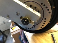
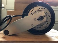
Right now I'm working out a design for torque plates to replace the clamping dropouts on the rear of the SB Cruiser trike, and allow me to put my hubmotor wheels in from the side, instead of from underneath, which will make it much easier for me to work on the wheels or tires on those occasions I do need to, since I won't have to lift or tip the trike to do it, since my back/hip is still healing but will probably never be like it was.

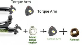
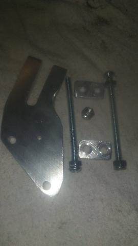
Basically it's just about a 2.5" square steel plate, at least 1/4" thick (thicker if I can do it, or doubling up the plates, for more axle-flat-to-hole-flat interface), with an axle hole in the center a lot like what you have there, but with disc-caliper mounting tabs to isntall Avid BB7's back there like I have in front (since I can't rely on regen brakign in all situations especially with the Grinfineon controllers (since if a hall goes out they switch to a mode that has no braking).

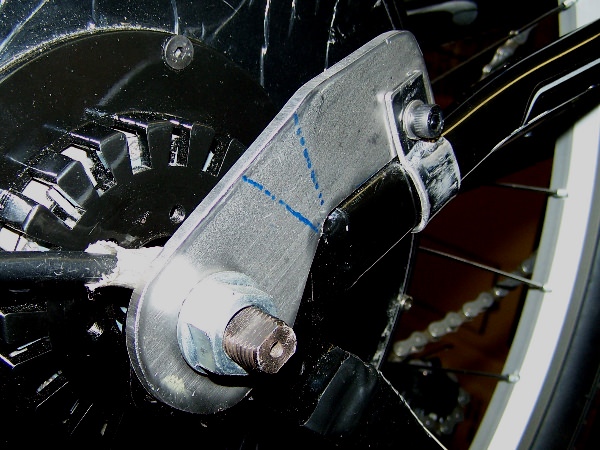
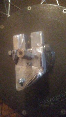
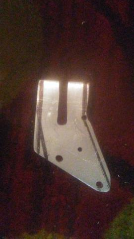
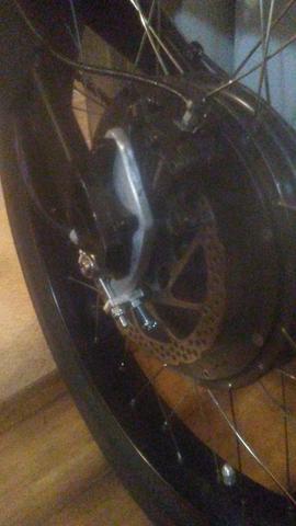
Kinda looks like this, but probably with the disc tabs on the right edge instead of top:
torque plate napkin sketch.png

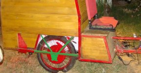
There will be four plates, two of which will be outboard and welded to a section of frame that's removable, bolted to the rest of the trike frame, highlighted in green. The disc brakes are mounted there, under the lower "rail", with the rightside one forward of the wheel, and the leftside one rearward of the wheel, so that the calipers can be the same (already have them) and so can the mounting plates. The inboard plates will be welded to the main trike frame, in place of the clamping dropouts that are there now. They will still have disc tabs because it's easier to have them all made the same, most likely.

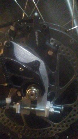
I have to setup a motor, rotor, caliper, etc., in a picture so I can then trace that out and measure stuff and build it in a CAD program, so I can get these made. (I planned to do them by hand, but worked out that it will probably take me weeks, at least, to do them myself, with the time and energy I have available).
 

Attachments

  • DSC07854wheelmount - Copy.JPG
    DSC07854wheelmount - Copy.JPG
    87.9 KB · Views: 2,690
  • DSC07854wheelmount.JPG
    DSC07854wheelmount.JPG
    118.1 KB · Views: 2,690
John in CR said:
auraslip said:
That derailluer hanger looks like butter compared to my 1/4" steel torque plate of approximently the same size that only lasted half a mile.

Many of the motor axles are pretty soft too, so hard steel in the torque arm or dropouts may not help. Thickness for more contact area is what matters, and if you have regen, you better have a clamping type.

John, it seems like you are the resident expert for using high powered hubs safely and reliably. If you say clamping torque arms are the only option, I will believe you and start planning a clamping torque arm design on my next bike. I know you've covered it hundreds of time by now, so I feel bad suggesting it, but you should consider doing a FAQ on making them for everyone else.

Just because I harp on something doesn't make me an expert, but I do make sure my hubmotor wheel can't fall off. I make torque dropouts, not add-on torque arms, but the concept is the same. Here are some pic. Some are 5/8" per side and some 9/16" per side:
Clamping dropouts.JPG
Front and rear .625in dropouts b.JPG
Front and rear .625in dropouts c.JPG
Front and rear .625in dropouts d.JPG

why the little hole and hacksaw cut from the clamping area, is that to help in clamping pressure or a controlled stress crack?
 
goatman said:
why the little hole and hacksaw cut from the clamping area, is that to help in clamping pressure or a controlled stress crack?

The hole was to prevent a stress crack, but I haven't done the drill holes, since the 2 earliest pairs of torque dropouts, as they're probably unnecessary with steel. The cut was to put more even clamping pressure on the flats. I've revised the approach and haven't needed to do the cuts the last 5 or 6 bikes. One mod is much deeper dropouts to go to 2 clamping bolts on each (I'm lazy about checking, and found a loose bolt once.). With 2 per side none have ever been loose (no loctite anymore either). I make them too tight at first and carefully with a file open them up to a tap in fit. I always use moto or scooter tires with which I can always get home or to a station as it takes a mallet on the tire or tapping with a hammer on a loosened nut to get the axle free of the bike.

If the fit ends up too loose, which did happen with one dropout since those early days, then I'll do a slice with the hacksaw to get a better squeeze across the axle flat with the clamp.

On my last 2 builds I went with an easier approach. I build the swingarm with 2"x1" rectangular tubing and 2"x1/4" flat stock near and past the ends. Then I clamp 1 piece of 3/4" square stock to each axle flat and to the swingarm flat stock and tack weld in place, remove the wheel and fully weld those in place. They are the top piece of the dropout for horizontal dropouts. Then I clamp the motor on including the matching 3/4" square stock for the solid end axle, and weld it in place. The holes on the top pieces and threaded holes on the bottom pieces of 3/4" are drilled and tapped before any dropout welding. The dropout installation is done at the end of the frame welding, so I can install swingarm and the fork and front wheel when doing the dropouts to ensure perfectly true wheel alignment.

The bottom piece of 3/4" solid stock for the wire side is bolt on only, both to the swingarm flat stock and to the top piece of 3/4" 1 in front of and 2 bolts behind the axle to clamp on the flat and hold it in place. On my motors that are meant for scooters, the axle flats are on 2 different planes. I used to modify the solid side axle to get the flats on the same plane, but wheels were still hard to get off.

I will try to remember to take some pics tomorrow.
 
I made this out of 1 inch aluminum plate. set my circular saw at 1/4 inch depth cut to recess the mating surface so it grabs the outside of the drop out plate. the clamping bolt I drilled a little low so I could file the motor shaft/axle so its a tight fight to the shank of the bolt.

vd2a0DC.jpg


Gbd6UJp.jpg


2HsbuTK.jpg


8QwyHFh.jpg
 
I saw this style a couple pages back. I needed to space my brake toward the motor.
3/8 aluminum plate. the first pic the legs were 1 inch wide and wouldn't budge so I trimmed them to 5/8 inch and now it clamped

u1qxiqi.jpg


TRXuYTJ.jpg


LiM5pib.jpg


x2LH3hh.jpg


agPQkUM.jpg


I used 1/4 inch machine screws and 1/4 inch aluminum plate for clamping and it clears the disc rotor by 1/8 inch.
 
Back
Top